|
Think & Tinker, Ltd.
P.O. Box 1606, Palmer Lake, CO 80133
Tel: (719) 488-9640, Fax: (866) 453-8473
Sales: Sales@thinktink.com, Support: Support@thinktink.com
|
|
Think
&
Tinker
Ltd.


SkypeMe at
"thinkntink"
|
PREVIOUS  NEXT
Getting Things Ready/Unpacking
Getting things ready
Unpacking
- While unpacking the crate, inspect the unit for damage. If any damage is found, report it to Think & Tinker immediately.
- Place the cart in a well-lit, well-ventilated workspace.
- Unpack all of the system components and inspect them for damage. As above, if any damage is found, report it to Think & Tinker, Ltd. immediately.
- The board clamp is taped to the inside of a cart leg. Remove the tape, but leave the clamp in place until you are ready to leach the tank.
 Float Switch
Fig. 2
- Remove the rubber band from the float switch (fig. 2). Be very careful not to dislodge the float or twist the body of the switch as this might cause
the seal to leak. The float switch is used as a safety switch to control the power feed to the temperature controller. The float switch is connected to a relay that breaks the AC line if the solution level drops below the center of the switch. The contacts in the switch are intended for pilot (low current) application only. Never try to control a heater directly with this float switch.
- Set the tank cover plate into place with the ribs facing down into the
tank. The sparger riser pipe should feed through the 3/4 in.
dia. hole in the plate. Set the air-supply elbow fitting into place
on top of the riser and press down while twisting the fitting back and forth. The riser will seat itself into the fitting.
Do not glue the fitting in place, as it may need
to be removed if the system ever needs service.
- Because of the wide variation in air supply systems, you will have to supply
your own coupling to connect the air line to a source of CLEAN, DRY compressed air. The unit is provided with 10 ft. of ¼ in. polyethylenetubing
with a compression style connector already installed.
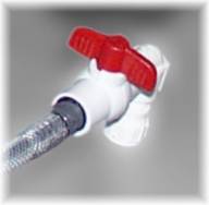 Drain valve closed
Fig. 3
- If you are using shop air (air compressor feeding a storage tank), you must
use a filter to insure that the air stream is free of dust, dirt and oily aerosols. Attach the air tube to your air
supply through a filtered regulator fitted with a needle valve to control the volume of sparging air. Position a "master shut-off"
valve between the pressure regulator and the needle valve.
- If you are using a regenerative blower as a dedicated source of compressed air for your developer, a "by-pass" valve should precede the air valve. With this setup you will increase bath agitation by slowly closing the by-pass valve until the desired degree of bath turbulence is achieved. This will maximize the amount of air flowing through the compressor, letting it run cooler and more efficiently.
- Before proceeding, make sure that the drain valve is closed and the PVC cap is screwed into place at the end of the drain hose (fig. 3)
PREVIOUS NEXT |

 |
Established 1990
On the web since 1994
|
Sales: 1-(719) 488-9640 Tech Support: 1-(719) 488-9640 Fax: 1-(866) 453-8473
Copyright © 1994 - 2014 Think & Tinker, Ltd.
|
|
 Home
Home